Bathroom Heater Light Fan Mini Installation
IMPORTANT: The AUPU 3 in 1 Bathroom Heater must be installed to comply with the appropriate council regulations and the local wiring rules or latest edition thereof.
Order Mini Bathroom Heater Light Fan here
A licensed Electrician is required to connect this unit to the mains supply.
The main supply and interconnecting cables required for installation of this appliance are not included, suitable cabling no lighter than ordinary duty cable rated at a minimum 10 Amp load rating is to be used
when installing / wiring this appliance.
WARNING
1.Use this heater only as described in this manual. Any other use not recommended by the manufacturer may cause fire, electric shock, or injury to persons. If you have questions, contact the manufacture or local
agent.
2. All wiring must be carried out by a Licensed Electrician in accordance with all applicable National / local codes and standards. Also check with the local council regulations regarding installation of exhaust fans.
3. Make sure the power is off before the installation.
4. When cutting into the wall, do not damage electrical wiring and other hidden utilities.
5.The heater must be properly grounded.
6.The lamps are hot when in use. Do not touch the infrared lamps with any part of your body when in use.
Allow all lamps to cool sufficiently before touching or replacement.
7.For the purpose of avoiding any dangerous gas leaking into your bathroom, the ventiduct of the heater must not be laid together with the ventiduct of air-fueled water heater or other open-fire appliances into the
same flue.
8. The heater must be isolated from the power by means of a plug or all-pole disconnection switch with a contact separation of at least 3mm in each pole.
9. The power cable must stand a minimum 5A load.
IMPORTANT CONSIDERATIONS BEFORE INSTALLING
A few minutes planning can make a big difference to the installation time and also to your satisfaction with the function of the unit.
1. The unit should not be installed directly above shower or bathtub. The unit must not be installed in a position where water may splash onto the lamps.
2. The heater must not be installed beneath a fixed socket.
3. The unit is designed for installation in flat ceilings only. Don’t mount it on a sloping ceiling or a vertical wall.
4.The infrared lamps are most effective when you are standing directly beneath them, so generally the unit would be mounted a place where you would stand to dry yourself.
5. For the exhaust fan to work efficiently, replacement air of a volume equivalent to what is being extracted must be able to enter the room. In general this air would be drawn under the door, or through a slightly
open window. If the room is airtight, the fan will function poorly.
6. Before commencing any cutting, check in the ceiling space that there are no obstructions such as ceiling joists and that there is sufficient height clearance for the housing. Check that the electrical wiring can be routed from the wall switches to the mounting location.
INSTALLATION
1. Cutting a vent (when required)
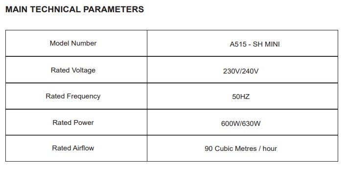
For installation where external venting is required or is your choice, locate a suitable location in either the roof or exterior wall to vent out the exhausted air / steam and cut out a 105mm hole.
2. Ducting
Put one end of the 100mm diameter ventiduct into the vent hole and seal space around the hole using a suitable sealant and cowling where necessary.
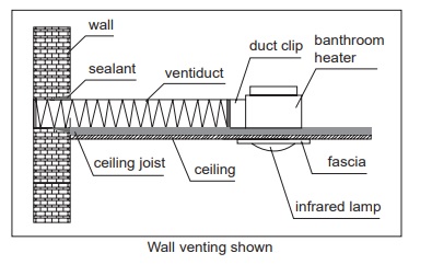
Note: Since the length of each duct is 1.5m, make sure that from the center of installation position there should be a distance within 1.5m to the outside vent.
3. Locating the heater
For the purpose of obtaining best heating effect, from the lamps there should be about a 2.3m overall height to the ground.
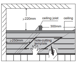
4. Prepare the ceiling
Using this instruction card as a template, mark the
ceiling with a pencil outline and cut out a hole in the
ceiling at the chosen area.
Make sure a distance between the edges and wall is no less than 250mm. Also from the rooftop there should be a minimum 220mm height to the ceiling.
Ensure that the intended hole will have suitable room to
locate the unit and will not foul on joists or not fit in the
headroom provided.
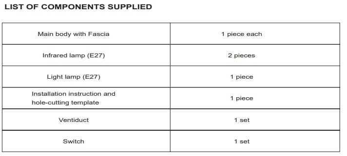
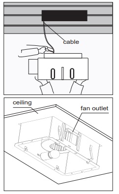
5 Remove the Fascia
Remove all lamps from the unit. Unclip the internal fascia-retaining springs inside the housing. Remove the fascia. Be careful not to damage the lamps when removing, storing or replacing.
Remove the fan outlet from housing.
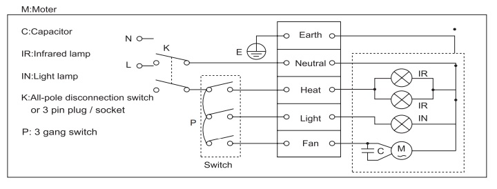
6.Wiring (Ensure that the power is turned off before carrying out any work on electrical installations)
Using suitable cable/s wire the 4 gang wall mounted switch with the active line via a suitable isolating switch or power outlet, as shown below, run the cable through the wall cavity to the ceiling for connection to the bathroom heater lamp. Connect the wiring to the terminal block in the bathroom heater lamp, as per the wiring diagram below, run the neutral line to the bathroom heater unit neutral connection via the
isolating switch or power outlet as used for the active line. Connect and ensure that the earth connections
on the unit are properly grounded.
Once the wiring is connected, replace the terminal cover on the bathroom heater lamp unit and locate the cabling so as to allow room for the bathroom heater lamp unit to be positioned in the ceiling cavity.
7. Fit the in-house end of the duct to the fan outlet,
and fix the end with duct clip.
Note: Keep the route as straight as possible.
8. Position the housing into the hole
Choose an optimal direction to put the housing into the
hole in accordance with the position of fan outlet.
Use the two spring clips to fix the housing.
Push the body of the unit into the hole in the ceiling, duct
side first, pull the spring clips inward to avoid damage to
the ceiling, then release so the spring clips can grip.
Ensure that the unit is held securely by the clips. If
required, screws may be used to aid holding the unit in
the ceiling. Some screw holes are provided in the housing
for this purpose.
Note: Try to keep the redundant wire away from the
housing
9. Final Installation
1) Replace the Fascia
Replace the fascia and retaining springs.
2) Replace the Lamps
Ensure the lamps are tightened sufficiently to make good
electrical contact. Clean the lamps and fascia.
3) Fix the Switch Panel to the wall
Depending upon the location and type of material the switch is to be fitted to, a switch bracket, (not supplied), may or may not be required. Fit the switch to the wall and replace the fascia plate.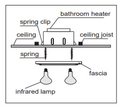
Note: The switch wiring should be routed inside the wall to give the switch and integrated built in
appearance. If it is necessary to run the wiring on the outside of the wall, use a suitable conduit and fixings
to properly locate and hold the wiring used.
USE
Our bathroom heater uses the infrared heating lamps as a source of heat. It also combines the functions
of exhaust and light.
1. Heat
Turn on/off ‘Heat’ button/s.
Each individual infrared lamp has been sprayed with 4ć ice water to ensure that there are no flaws in the
construction.
Note: Do not touch the infrared lamps with any part of your body when in use.
2. Exhaust Fan
Turn on/off ‘Fan’ button.
The heater can exhaust odours and steam in a quick and efficient way by turning on the ‘Fan’ button.
Note: No additional exhaust fan is necessary for the heater itself satisfies your need for exhausting in
bathroom.
3. Lighting
Turn on/off ‘Light’ button.
MAINTENANCE
1. Clean
1) Shut off power before cleaning.
2) Wipe lamps and fascia with care using a soft cloth soaked with neutral detergent.
Ensure the lamps are cool to touch before handling.
2. Lamp Replacement
1) Check and tighten lamps regularly.
2) Shut off power before replacement.
3) Use an E27 maximum 60W reflector lamp for lighting.
4) Use E27 275W infrared lamps for heating.
Note: It may affect operation (even cause danger) when use of lamps is other than the designated ones.
WARRANTY
The AUPU 3 in 1 Bathroom Heater is warranted against defects in manufacturing and workmanship for a
period of 36 Months. The warranty does not extend to lamp globes supplied or installation of the unit or
any associated wiring or any damage caused by installation or wiring.
The installation must be conducted by a licensed electrician and a suitable certificate of safety is to be
issued by the electrician who installed the unit. Warranty claims will be voided unless a certificate of safety
can be produced when required, prior to service or repair.
Please keep and present the original invoice to your service agent for warranty services.
This warranty does not cover damages or loss caused by:
1) Heat or light lamps.
2) Any consequential losses arising from incorrect installation or operation or maintenance of this product.
3) Any consequential losses arising from incorrect wiring of this product.
4) Any modifications or changes make to the unit, other than those recommended by the Manufacturer.